Understanding PLC Components: CPU, I/O, and Power Supply Explained
As an industrial automation partner, we often see engineers get lost in system complexity without fully grasping the fundamentals of the hardware they operate. Understanding the core components of a PLC—CPU, I/O, and Power Supply is not just about theory. It is the key to rapid troubleshooting and efficient system design.
Here is an in-depth guide on PLC anatomy, drawn from our experience deploying and maintaining thousands of control systems in the field.
The Core Components of a PLC: The Anatomy of Industrial Automation
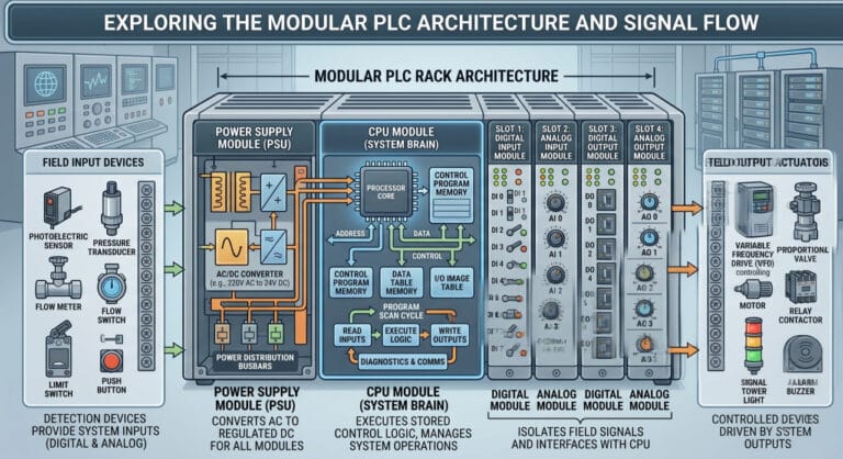
In the era of Industry 4.0, the Programmable Logic Controller (PLC) remains the gold standard for control reliability. However, this reliability is entirely dependent on the health of its three main pillars: the Central Processing Unit (CPU), Input/Output (I/O) modules, and the Power Supply. As practitioners, we view a PLC much like a human body; if one organ fails, the entire system collapses.
Microprocessor (Processor Core): This is the engine that executes logic (math functions, timers, counters, and PID loops) in microseconds. The processor’s speed is critical to preventing delayed interlocking on high-speed machinery.
Modern Memory System (RAM & Flash/EEPROM): Modern PLCs have moved beyond obsolete ROM. Today, we use Flash Memory or EEPROM (non-volatile) to store the engineer’s master program so it remains intact during a power collapse. Meanwhile, RAM stores dynamic data—such as the I/O image table, register values, and process variables—that change every millisecond.
Communication Port (Integration Gateway): These ports are not just for downloading programs. Modern communication ports (such as RJ45 for Ethernet/IP and Profinet, or RS485 for Modbus RTU) handle horizontal data exchange between PLCs and vertical transmission to HMI, SCADA, and IoT gateways.
The Execution Mechanism: The Three-Stage Scan Cycle
The responsiveness of a PLC relies heavily on its Scan Cycle. The CPU operates this cycle continuously through three rigid, sequential stages:
Read Inputs (Field Data Acquisition): The CPU copies the physical status of all digital inputs (e.g., limit switches) and analog inputs (e.g., pressure transmitters) into the RAM, known as the Input Image Table. The CPU does not poll sensors mid-program; instead, it relies on this “snapshot” taken at the start of the cycle.
Execute Program (Logic Processing): The processor executes the code (whether Ladder Diagram, Structured Text, or Function Block) from top to bottom and left to right. It uses the snapshot data stored in the RAM to calculate interlocks and safety logic.
Write Outputs (Command Update): Once the program calculation is complete, the CPU updates the Output Image Table in the RAM. It then sends physical electrical signals to the output modules simultaneously, triggering actuators such as solenoid valves or contactors.
Field Insight: If your program structure is too “heavy” or contains inefficient looping instructions, the Scan Cycle time will swell beyond system tolerances (e.g., exceeding 50 ms). The result? Unacceptable response delays that can trigger mechanical failures or trip factory safety systems.
Read More: Examples of PLC Applications: How PLCs Work in Industrial Settings
Practical Field Insights
Based on our experience, CPU issues rarely stem from hardware failure. Instead, they are usually caused by Memory Overflow or excessive Scan Cycle times resulting from inefficient program logic. Selecting a CPU with the appropriate memory capacity is critical to preventing system “lag” during high-speed processing.
2. Input/Output (I/O) Modules: The Bridge Between Digital and Physical
I/O modules are the interface between the digital controller and physical factory-floor devices. Without these modules, a CPU is merely an isolated computer.
Input Modules (The System’s Senses)
Inputs receive signals from the field. They are categorized into two types:
- Digital Input: Receives ON/OFF signals (e.g., push buttons, limit switches, or proximity sensors).
- Analog Input: Receives variable values, typically within the 4-20mA or 0-10V range (e.g., temperature or pressure sensors).
Output Modules (The System’s Muscles)
Outputs transmit commands from the CPU to execution devices:
- Digital Output: Starts or stops devices (e.g., turning on indicator lights or actuating solenoid valves).
- Analog Output: Provides precise control (e.g., adjusting motor inverter speeds or positioning control valves).
Practical Field Insights
The most common mistake we encounter is voltage mismatch in I/O modules. Using PNP sensors on NPN modules (or vice versa) is a classic “trap” for junior engineers. Additionally, utilizing Optical Isolation on I/O modules is crucial to protect the CPU from electrical noise originating from high-power motors in the field.
3. Power Supply: The Often Overlooked Energy Foundation
The Power Supply Unit (PSU) converts incoming AC voltage (e.g., 220V) into stable DC voltage (typically 24V) to power the CPU and I/O modules.
Vital Characteristics of a PLC Power Supply
Many mistakenly view the power supply as a secondary component, yet it is the primary determinant of system stability:
- Voltage Regulation: Must remain highly stable, as the CPU is extremely sensitive to voltage ripple or fluctuations.
- Current Capacity (Amperage): Must be sufficient to power the total load of all I/O modules plus connected field sensors.
- Protection: Must feature integrated Short Circuit Protection and Overvoltage Protection.
Practical Field Insights
Never size your power supply exactly to the calculated load. We always advise clients to maintain a 20-30% capacity headroom. A power supply pushed to its limit generates excessive heat, and heat is the primary enemy of electronic component longevity.
Case Study: Resolving Unplanned Downtime in a Cement Plant
A client’s cement plant was plagued by a persistent issue: the PLC would frequently reboot without warning (intermittent failure). Their internal engineering team had already replaced the CPU twice, yet the problem remained unresolved.
Our Analysis: After conducting a thorough audit, we confirmed that both the CPU and I/O modules were functioning correctly. The root cause was the Power Supply, which had been in operation for five years. Whenever the facility’s large motors started, the main line experienced a voltage dip. The aging power supply could no longer maintain a stable 24VDC output during these surges, causing the CPU to trigger an emergency reboot to protect data integrity.
The Solution: We replaced the power supply with an industrial-grade unit equipped with a Buffer Module (a large capacitor bank designed to maintain voltage during momentary dips). The Result: Unplanned downtime was eliminated, saving the plant hundreds of millions of rupiah previously lost to control system failures.
Conclusion: Building Resilient Industrial Systems
Understanding the core components of a PLC—CPU, I/O, and Power Supply—in detail allows you to build systems that are not only functional but also highly resilient. As an engineer, your priority must be selecting compatible components that provide an adequate safety margin.
Quick PLC Procurement Checklist:
- CPU: Is the memory capacity sufficient for program expansions over the next 5 years?
- I/O: Do the signal types (PNP/NPN/Analog) align perfectly with your field sensors?
- Power Supply: Does the amperage capacity provide enough headroom for the total system load?
Berikut adalah terjemahan yang SEO-friendly, persuasif, dan tetap menjaga kredibilitas teknis lo:
Seeking a Robust, Efficient, and Durable PLC Architecture?
Don’t let your critical industrial control systems fail. Building a truly resilient PLC architecture (CPU, I/O, and Power Supply) requires careful planning, deep technical expertise, and long-term foresight.
At Folks Automation, our team of experts is ready to help you design a precise and reliable PLC system from the ground up. We ensure seamless component compatibility, adequate safety margins, and detailed 5-year expansion roadmaps.
Don’t wait for a system failure. Consult with our specialists today and optimize your industrial performance.