

Understanding the Differences in PLC Programming Languages: LD, FBD, ST, and IL for Industrial Automation

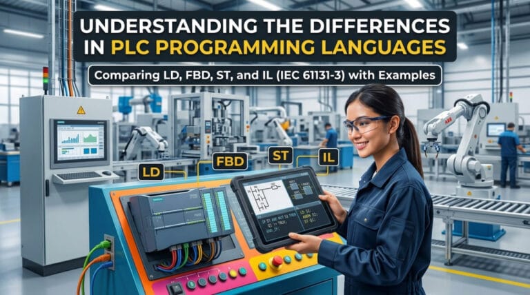
In designing a Programmable Logic Controller (PLC)-based control system, selecting the right programming language determines program execution efficiency, ease of troubleshooting, and long-term maintenance costs. The international standard IEC 61131-3 establishes several standard programming languages for industrial controllers, the most common being Ladder Diagram (LD), Function Block Diagram (FBD), Structured Text (ST), and Instruction List (IL).
Although all of these languages can produce the same control logic at the memory processing level, their syntax structures and presentation styles differ significantly. This article breaks down the architecture, advantages, and comparative script studies for each language.
1. Ladder Diagram (LD) – Electrical Relay-Based Logic Visualization
Ladder Diagram is the most popular PLC programming language because it adopts the visual symbols of relay schematic diagrams (relay ladder logic). The program structure is arranged vertically to resemble a ladder, where the left vertical line represents the power rail and the right vertical line represents the neutral.
Characteristics & Usage
- Visualization: Uses normally open (NO) contacts, normally closed (NC) contacts, and coils.
- Pros: Highly intuitive and easy to understand for field electrical technicians without a computer programming background.
- Cons: Inefficient for complex mathematical calculations, string manipulation, or data array processing.
Logic Script Example (Motor Start/Stop Latch)
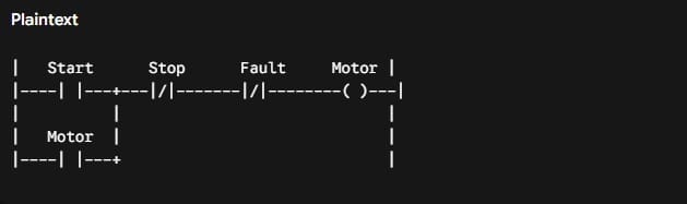
This Ladder Diagram rung is the most basic visual representation of a latching/self-holding circuit equipped with interlock protection in a PLC.
Symbol Anatomy in the Rung
- | | (Normally Open / NO): Open switch contact. Logic electrical current can only pass if the signal value is 1 (pressed or activated).
- |/| (Normally Closed / NC): Closed switch contact under normal conditions. Logic electrical current can pass as long as the signal value is 0 (unpressed/no fault).
- ( ) (Output Coil): Physical output coil that will evaluate to 1 (ON/Energized) if there is a continuous current path from the leftmost rail.
Detailed Logic Workflow
- Parallel Start & Motor Path (Latching Function)
- The Start button is wired in parallel with the auxiliary Motor contact.
- When Start is pressed (1), current flows through Start $\rightarrow$ Stop $\rightarrow$ Fault $\rightarrow$ triggering the Motor Coil to turn ON (1).
- As soon as the Motor Coil activates, the NO Motor contact on the lower path also closes (1).
- When the Start button is released (0), the logic electrical current is not interrupted because it shifts to flow through the lower path (Motor contact). This keeps the motor running without needing to hold the button continuously.
- Stop Contact (|/|) – Latch Breaker
- Connected in series using a Normally Closed contact.
- Under normal conditions (unpressed), the Stop variable value is 0, keeping the |/| contact closed and allowing current to pass.
- When the Stop button is pressed (1), the |/| contact opens. The current path is completely broken, the Motor Coil turns OFF (0), and the lower latching path automatically unlatches.
- Fault Contact (|/|) – Primary Protection
- Functions as a safety mechanism (e.g., connected to a thermal overload relay or temperature sensor).
- As long as the system is safe (Fault = 0), the contact remains closed.
- If an issue occurs in the field (Fault = 1), the |/| contact immediately opens and shuts off the motor instantly, overriding both the Start button and the Motor latching status.
Condition Simulation Matrix
| Action / Status | Start | Motor Contact | Stop (Input) | Fault (Input) | Motor Output |
| Standby | 0 (Open) | 0 (Open) | 0 (NC Closed) | 0 (NC Closed) | OFF |
| Press Start | 1 (Closed) | 0 $\rightarrow$ 1 | 0 (NC Closed) | 0 (NC Closed) | ON |
| Release Start | 0 (Open) | 1 (Closed) | 0 (NC Closed) | 0 (NC Closed) | ON (Latched) |
| Press Stop | 0 (Open) | 1 $\rightarrow$ 0 | 1 (NC Open) | 0 (NC Closed) | OFF |
| Trip / Fault | 0 (Open) | 1 $\rightarrow$ 0 | 0 (NC Closed) | 1 (NC Open) | OFF (Tripped) |
Ladder logic patterns like this serve as the standard industrial foundation for safely controlling 3-phase motor magnetic contactors.
2. Function Block Diagram (FBD) – Logic Block-Based Signal Processing
Function Block Diagram presents the program as integrated function blocks connected by signal lines. FBD represents continuous data flow from inputs on the left to outputs on the right.
Characteristics & Usage
- Visualization: Logic gate function blocks (AND, OR, NOT), timers, counters, and PID blocks.
- Pros: Highly intuitive for linear process control systems, analog signal processing, and safety systems.
- Cons: Consumes significant screen space as programs become highly complex, making navigation difficult.
Logic Script Example (Motor Start/Stop Latch)
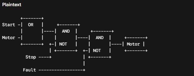
This FBD (Function Block Diagram) represents Start/Stop Latching logic with Protection Interlocks (Stop & Fault) to control the Motor output.
Signals flow from left (Inputs) to right (Outputs) through 3 logic stages:
- Initiation & Latching Stage (OR Block)
- Input: Start button and Motor status feedback signal.
- Operation: The OR block evaluates to 1 (TRUE) if the Start button is pressed or if the Motor is currently active.
- Function: Creates a latching system. When the Start button is released, the signal from the OR block remains 1 because it latches the status of the running Motor.
- Stop Button Interlock Stage (NOT + First AND Block)
- Input: Output from the OR Block and the Stop button signal passed through a NOT gate.
- Operation: The Stop signal is inverted by the NOT gate. Under normal conditions (Stop button unpressed = 0), the NOT output is 1.
- First AND Result: The Motor can only receive a run signal if (Start/Motor Active) AND (Stop is NOT pressed). As soon as the Stop button is pressed (1), the NOT output becomes 0, breaking the signal at the first AND block and killing the latch.
- System Protection Stage (NOT + Second AND Block)
- Input: Output from the First AND Block and the Fault signal (e.g., from thermal overload) passed through a NOT gate.
- Operation: The Fault signal is inverted by the NOT gate. Under safe conditions (Fault = 0), the NOT output is 1.
- Second AND Result: Serves as the final safety stage. The Motor turns on ONLY IF the path from the Start/Stop command is clear AND there is no system fault (Fault = 0).
- Output Execution (Motor)
- The final logic signal energizes the physical Motor output. This value is simultaneously fed back to the OR Block input at the initial stage as a latching signal.
Field Workflow Simulation:
- Start Pressed: Start (1) $\rightarrow$ OR (1) $\rightarrow$ NOT Stop (1) $\rightarrow$ AND1 (1) $\rightarrow$ NOT Fault (1) $\rightarrow$ Motor ON (1).
- Start Released: Start (0), but Motor (1) $\rightarrow$ OR remains (1) $\rightarrow$ Motor Stays ON (Latching active).
- Stop Pressed: Stop (1) $\rightarrow$ NOT Stop (0) $\rightarrow$ AND1 (0) $\rightarrow$ Motor OFF (0) (Latching signal broken).
- Overload/Trouble Occurs: Fault (1) $\rightarrow$ NOT Fault (0) $\rightarrow$ AND2 (0) $\rightarrow$ Motor Instant OFF (Protection active, ignoring Start/Stop status).
3. Structured Text (ST) – Text-Based High-Level Programming
Structured Text is a high-level, block-structured text-based programming language similar to Pascal or C. ST is designed to handle complex algorithmic tasks that are difficult to execute using graphical languages.
Characteristics & Usage
- Visualization: Uses conditional statements such as IF-THEN-ELSE, CASE, as well as FOR and WHILE loops.
- Pros: Highly efficient for complex mathematical operations, protocol data communication, matrix handling, and recipe management.
- Cons: Requires an understanding of text-based programming and is more difficult to debug visually for field technicians.
Logic Script Example (Motor Start/Stop Latch)

This single line of Structured Text (ST) code is the most concise version of a Start/Stop Latching control system with interlock protection. All latching, breaking, and safety logic—which typically requires multiple rungs in a Ladder Diagram—is condensed into one boolean mathematical expression.
Anatomy and Code Components
- Motor := This is the assignment operator. The result of the logic calculation on the right side of := will be directly sent to execute the Motor output state (TRUE or FALSE).
- (Start OR Motor) — Latching Function: The expression inside the parentheses is evaluated first. It evaluates to TRUE if the Start button is pressed OR if the Motor is already running. Once the Motor is active, Motor = TRUE self-latches, making it safe to release the Start button.
- AND NOT Stop — Interlock Breaker: This part ensures the Stop button is inactive (Stop = FALSE). If the Stop button is pressed (TRUE), NOT Stop turns to FALSE. Because it uses an AND gate, this FALSE value immediately forces the entire expression to FALSE, breaking the latch.
- AND NOT Fault — Primary Protection Interlock: Functions as the system safety check (e.g., against thermal overload or emergency stop). If an issue arises (Fault = TRUE), NOT Fault becomes FALSE. The system instantly turns off the motor regardless of the Start or Motor status.
Field Logic Evaluation Simulation
| System Condition | Logic Evaluation in Program | Output Status (Motor) |
| Press Start | (1 OR 0) AND NOT 0 AND NOT 0 $\rightarrow$ 1 AND 1 AND 1 | ON (TRUE) |
| Release Start | (0 OR 1) AND NOT 0 AND NOT 0 $\rightarrow$ 1 AND 1 AND 1 | STAYS ON (Latched by Motor) |
| Press Stop | (0 OR 1) AND NOT 1 AND NOT 0 $\rightarrow$ 1 AND 0 AND 1 | OFF (FALSE) (Latch broken) |
| Fault Occurs | (0 OR 1) AND NOT 0 AND NOT 1 $\rightarrow$ 1 AND 1 AND 0 | INSTANT OFF (Protection trip) |
Critical Implementation Notes for the Script
- Parentheses are Mandatory: Under the IEC 61131-3 standard, the AND operator has higher operator precedence than OR. Without parentheses around (Start OR Motor), the PLC would execute Motor AND NOT Stop AND NOT Fault first before OR-ing it with Start. As a result, motor latching would completely fail.
- Physical Button State (Hardware vs. Software): The NOT Stop script above assumes the physical field input is a Normally Open (NO) button. If industrial safety standards are used with a physical Normally Closed (NC) button, the script logic should be adjusted to AND Stop (without NOT).
4. Instruction List (IL) – Low-Level Assembly Language for Fast Execution
Instruction List is a low-level, line-by-line text language that resembles Assembly code. IL operates on accumulator-based instruction execution principles.
Characteristics & Usage
- Visualization: Sequential single-command lines (e.g., LD, AND, ST).
- Pros: High execution speed and minimal memory footprint on small-scale PLC hardware.
- Cons: Hard to read, prone to syntax/logic errors, and officially deprecated in modern updates of the IEC 61131-3 standard.
Logic Script Example (Motor Start/Stop Latch)
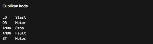
Comparative Table for Selecting a PLC Programming Language
| Criteria | Ladder Diagram (LD) | Function Block (FBD) | Structured Text (ST) | Instruction List (IL) |
| Visual Format | Graphical (Relays) | Graphical (Blocks) | Structured Text | Assembly Text |
| Troubleshooting Ease | Very High | High | Moderate | Low |
| Mathematical Calculation | Limited | Moderate | Very High | Low |
| Ideal Application | Discrete Control Logic | Process Control & PID | Algorithms & Data Processing | Small Memory Operations |
| Industry Adoption Rate | Highly Dominant | Dominant | Rapidly Growing | Declining (Deprecated) |
Optimizing Industrial Automation with Folks Automation
The suitability of the chosen programming language must be backed by reliable PLC hardware processing in the field. Folks Automation stands as the first local PLC manufacturer in Indonesia with extensive experience in utilizing PLCs for industrial automation systems.
As a domestic manufacturer, Folks Automation develops a flexible PLC ecosystem designed to support the IEC 61131-3 architecture. This allows engineers to combine multiple programming languages such as using Structured Text for precise mathematical calculations and Ladder Diagrams for safety interlocks within a single integrated control system. Key hardware and software integration advantages from Folks Automation include:
- Real-Time Processing: Stable instruction execution speed for high-speed applications.
- Local Architectural Support: On-site local engineering teams ready to assist with logic programming and system testing.
- Integration Efficiency: Seamless connectivity with digital/analog I/O modules and standard industrial communication protocols.
Consult Your Automation System
Is your team designing a new control architecture, facing challenges with PLC program conversions, or needing to optimize your production system logic? The expert team at Folks Automation is ready to provide technical support, evaluate program efficiency, and design the PLC solution best suited to your plant’s specific needs. Connect directly with the Folks Automation technical team via their official WhatsApp contact at: +62 821-1404-4968