

What Is a PLC? Understanding Its Role, Functions, and How It Works in Industry


A Programmable Logic Controller (PLC) is an industrial digital controller specifically designed to automate machines and production processes based on programmed logic. In simple terms, a PLC acts as the “brain” of a machine. It receives input signals, processes them according to a control program, and sends output commands to devices such as motors, valves, and alarms.
Brief History of PLC
PLCs were developed in the late 1960s to meet the growing operational demands of industrial production. Before PLCs, factories relied heavily on complex relay-based control panels. The first PLCs replaced traditional relay systems to improve efficiency, reduce wiring complexity, and simplify maintenance.
From basic start/stop ladder logic systems in the 1960s to modern smart automation integrated with IoT and smart factory technologies after 2010, PLC technology has continuously evolved alongside industrial advancements.
Why PLC Replaced Relay Systems
Before Programmable Logic Controllers (PLCs) became the industry standard, automation relied entirely on hardwired control panels packed with electromechanical relays, timers, and counters. While functional for basic operations, relay-based systems proved highly inefficient as manufacturing scaled. PLCs ultimately replaced relay systems due to four critical operational bottlenecks:
Lack of Data & Scalability: Relays can only turn devices ON or OFF; they cannot process continuous data, perform complex mathematical calculations, or store historical metrics. PLCs bridged this gap by handling advanced analog signals, PID control, and industrial networking needed for modern Industry 4.0 applications.
Complex Hardwiring & Space Constraints: Traditional relay logic requires physical wires for every single connection. A simple logic change meant manually rewiring hundreds of mechanical components, consuming massive control panel space and increasing structural failure points.
Maintenance & Mechanical Wear: Relays depend on moving physical contacts that degrade over time due to electrical arcing and friction. Troubleshooting a dead relay in a cabinet with thousands of wires often resulted in hours of costly machine downtime.
Inflexibility during Production Changes: Modifying a process in a relay system required physically redesigning the circuit board and stopping the production line. With a PLC, engineers simply update the Ladder Logic code in software—no rewiring required.
Core Functions of a PLC in Industrial Automation
To fully understand the role of a Programmable Logic Controller (PLC), we must examine how it functions as the central decision-maker on the factory floor. Instead of relying on human manual control, a PLC executes three fundamental operational tasks:
1. Sequential Machine & Actuator Control At its core, a PLC executes pre-programmed logic to coordinate complex machine operations in precise sequences. It continuously evaluates system rules before triggering outputs like motors, control valves, hydraulic pumps, or conveyor drives.
Operational Example: A conveyor belt only starts if the safety guard is fully closed AND the downstream packaging machine signals it is ready. If an emergency stop or overload signal trips at any point, the PLC immediately cuts power to prevent equipment damage or operator injury.
2. Signal Acquisition & Data Processing (Discrete vs. Analog) PLCs bridge the physical plant floor and digital logic by reading continuous electrical signals from field instrumentation. They process two distinct types of data:
- Discrete (Digital) Inputs: Binary signals representing two states—ON (1) or OFF (0). Used by limit switches, proximity sensors, and push buttons to confirm physical presence or position.
- Analog Inputs: Continuous variable signals (such as 4–20 mA current loops or 0–10V voltage). Used by thermocouples, pressure transducers, and flow meters. The PLC converts these raw continuous signals into engineering units (e.g., Temperature in °C or Pressure in PSI) to execute feedback loops like PID control.
3. Process Automation & Real-Time Fault Management PLCs ensure high-volume manufacturing runs continuously without direct human intervention, reducing human error and optimizing cycle times. Beyond basic automation, modern PLCs constantly monitor system health:
- Real-time Response: Detecting abnormal pressure spikes or temperature drifts within milliseconds and executing controlled shutdown sequences automatically.
- Interlocking & Safety: Guaranteeing that dangerous, conflicting operations (such as opening a discharge valve while a tank is still pressurized) cannot physically occur.
Real Examples of PLC Applications
While theoretical concepts explain how PLCs process logic, their real value lies in their practical implementation on the factory floor. From simple material handling to complex fluid processing, PLCs manage multi-variable environments where precise timing, safety interlocks, and continuous monitoring are mandatory. Below are two classic examples of how PLCs manage dynamic operations in real-world industrial environments:
1. PLC Control in Industrial Conveyor & Sorting Systems
In a modern distribution center or assembly line, a PLC does far more than just start or stop a motor it manages sequence, flow control, and fault detection in real time.
Presence & Positioning: Photoelectric sensors detect an incoming carton, signaling the PLC to ramp up the Variable Frequency Drive (VFD) controlling the conveyor motor.
Sorting & Diverting: Barcode scanners send product data to the PLC via Industrial Ethernet. The PLC tracks the package position along the belt and triggers a pneumatic pusher arm at the exact millisecond to route the box to its designated chute.
Jam Detection & Safety: If a sensor remains blocked longer than a defined threshold (indicating a package jam), the PLC immediately halts the upstream conveyor to prevent pile-ups and alerts operators via an HMI alarm.
2. PLC Control in Water & Liquid Tank Systems
In chemical processing, water treatment, or oil storage, precise liquid level control is essential to prevent dry-running pumps or catastrophic tank overflows.
Dual-Threshold Pump Control: The PLC receives continuous depth data from an ultrasonic level transmitter. When the fluid drops below a preset “Low Level” setpoint, the PLC energizes the supply pump contactor. Once the liquid reaches the “High Level” mark, it cuts power to the pump.
Hysteresis & Equipment Protection: To prevent the pump from rapidly cycling ON and OFF near threshold points (which destroys motor windings), the PLC applies programmed deadbands.
Safety Interlocking: If the tank hits a critical “High-High Level” due to a stuck valve, the PLC overrides manual controls, closes the main inlet solenoid valve, and activates an emergency drain procedure.
Main Components of a PLC
To fully understand what is PLC function, you must understand its core components.
1. Input Module
The input module receives digital or analog electrical signals representing physical conditions.
Inputs may come from:
- Sensors
- Push buttons
- Limit switches
Digital signals: ON/OFF
Analog signals: 0–10V, 4–20mA
The PLC stores these signals in internal memory before processing them.
2. CPU (Central Processing Unit)
The CPU is the brain of the PLC. It performs all decision-making tasks in a continuous loop called the scan cycle.
The CPU:
- Reads inputs
- Executes the control program
- Updates outputs
It processes logic operations such as:
- AND
- OR
- NOT
Programs, timers, counters, and parameters are stored in non-volatile memory, meaning they remain saved even when power is lost.
3. Output Module
The output module converts CPU decisions into real-world actions.
It controls devices such as:
- Motors
- Solenoid valves
- Indicator lamps
- Alarms
For example:
PLC sends ON signal → Contactor activates → Motor runs.
How PLC Works (Input → Process → Output)
The basic principle of PLC operation is:
Input → Process → Output
Step 1: Read Input
The PLC collects signals from sensors and switches.
Step 2: Execute Program
The CPU evaluates programmed logic thousands of times per second.
Example:
If Sensor A is ON AND Button B is pressed → Start motor.
Step 3: Write Output
The PLC sends commands to actuators such as:
- Motors
- Valves
- Lights
- Alarms
PLC Scan Cycle Explained
PLCs operate continuously in a repeating cycle:
- Read Inputs
- Execute Program
- Update Outputs
- Perform Housekeeping (communication updates, diagnostics, memory refresh)
Then the cycle repeats in milliseconds.
PLC Programming Languages (IEC 61131-3 Standard)
PLCs are programmed using internationally standardized languages.
1. Ladder Diagram (LD)
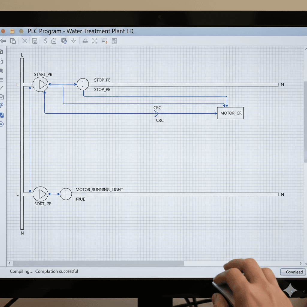
The most widely used PLC language.
It resembles electrical relay circuits.
Ideal for:
- ON/OFF logic
- Interlocks
- Start/Stop systems
2. Structured Text (ST)
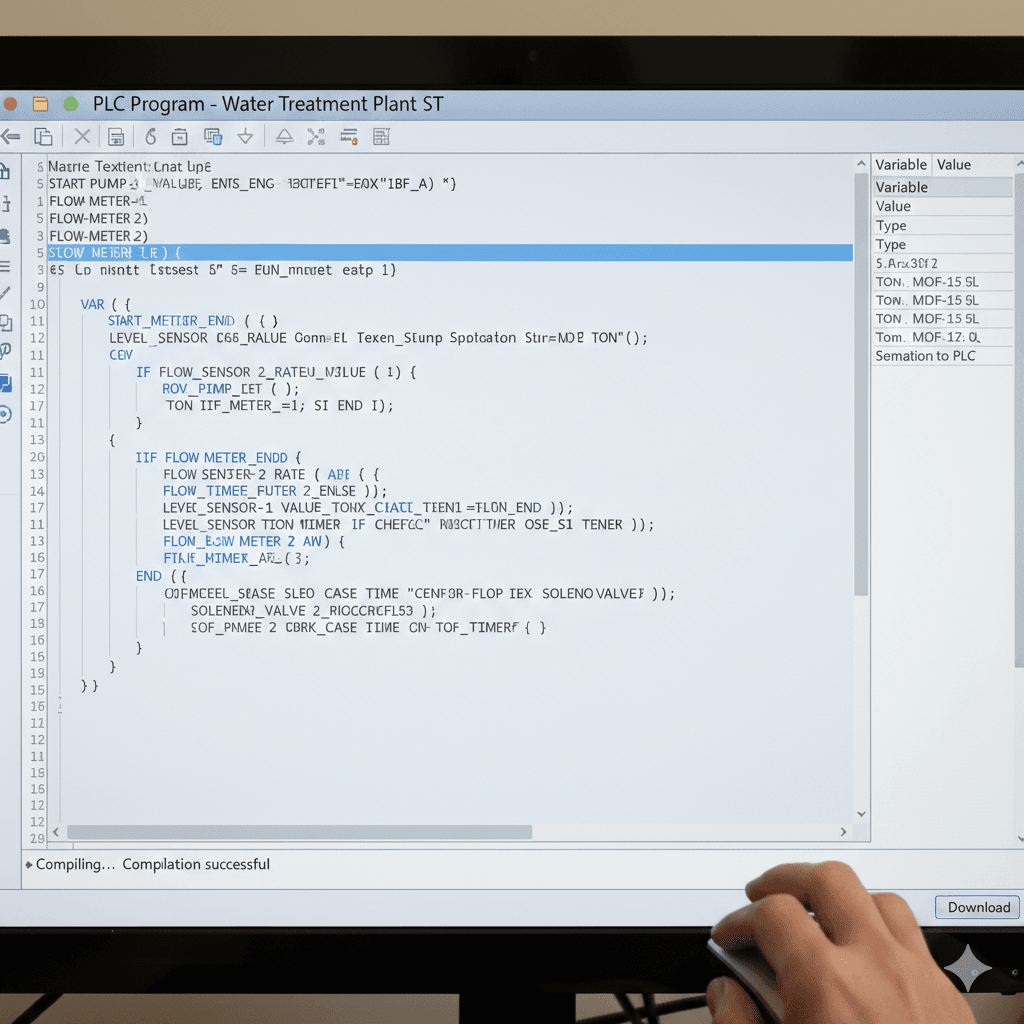
A text-based programming language similar to Pascal or C.
Used for:
- Mathematical calculations
- Complex algorithms
- Precision control
Example:
If temperature > 80 → Turn off heater.
3. Function Block Diagram (FBD)
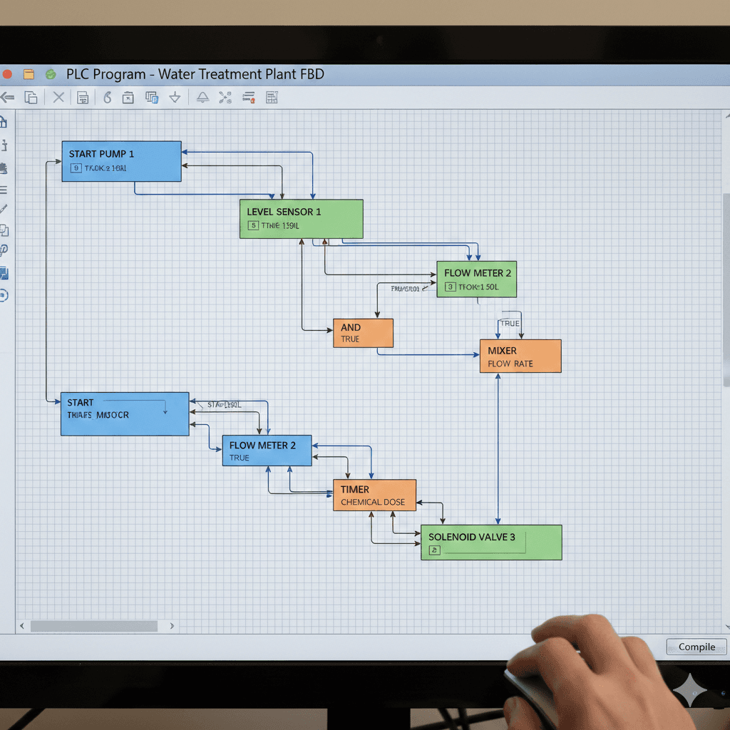
A graphical language using interconnected functional blocks.
Commonly used for:
- Process control
- PID control
- Analog systems
Advantages of PLC Over Conventional Systems
Flexible
Changing machine sequences does not require rewiring. You simply modify the program.
Example:
Changing pump delay from 5 seconds to 10 seconds only requires editing a parameter.
Designed for Harsh Industrial Environments
PLCs are built to operate under:
- High temperatures
- Dust
- Vibrations
- Electrical noise
They can run 24/7 inside control panels without failure.
Easy to Expand
When adding:
- More sensors
- Additional motors
- New automation features
You can simply add input/output modules and update the program.
Common Mistakes in PLC Implementation
Even though PLCs are reliable, problems often arise from improper implementation.
Ignoring Safety Systems
Many focus on machine functionality but neglect safety elements such as:
- Emergency stop systems
- Safety interlocks
- Protective sensors
PLCs must ensure both process control and operator protection.
Overcomplicated Programming
Complex logic is not always better. Over-engineered programs make troubleshooting difficult.
Good PLC programming is:
- Clear
- Structured
- Maintainable
Poor Documentation
Lack of:
- Ladder comments
- I/O descriptions
- Process flow documentation
Makes maintenance and future modifications difficult and risky.
Conclusion: Why PLC Is Essential in Industrial Automation
So, what is PLC function in modern industry?
A PLC serves as the intelligent control core of automated systems. Without PLCs, industrial processes would rely heavily on manual operation, resulting in slower production and higher error risks.
With PLCs, machines can:
- Operate automatically
- Follow consistent process sequences
- Respond to sensors in real time
- Maintain safety standards
- Adapt quickly to system changes
Because of its flexibility, durability, and scalability, the PLC has become the backbone of automation across industries—from food processing to heavy manufacturing. In today’s fast-paced industrial world, PLC technology makes automation efficient, reliable, safe, and adaptable.