How PLCs Work: A Simple Guide to Logic (AND, OR, NOT)

Many people think understanding automation requires a degree in engineering. However, learning how PLCs work, simple logic, and basic components is easier than you think. As outlined in our guide Cara Kerja PLC Secara Sederhana, understanding a Programmable Logic Controller (PLC) is actually quite simple.
At Folks Automation, we believe in making technology accessible. In this guide, we break down exactly how a PLC “thinks” and makes decisions using simple logic.
What is a PLC and Why Use It?
A PLC is essentially a rugged industrial computer designed to control manufacturing processes. Unlike a regular laptop, it is built to withstand harsh conditions like dust, moisture, and vibration.
Industries choose PLCs over standard computers because of their reliability. They are designed to run 24/7 without crashing, ensuring that factory lines never stop unexpectedly.
How a PLC Works (The Scan Cycle)
The secret to a PLC’s speed is a continuous loop called the Scan Cycle. It doesn’t just “run” code; it cycles through three specific steps thousands of times per second:
- Read Inputs: The PLC checks the status of all sensors and switches.
- Execute Program: The CPU runs the logic rules you have programmed.
- Update Outputs: The PLC turns motors, lights, or valves On or Off based on the rules.
The Main Components
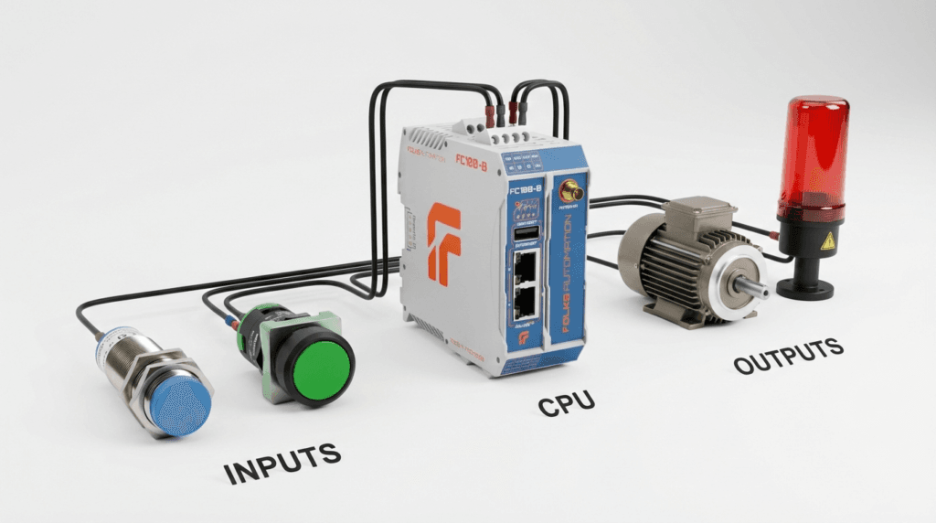
To function, every PLC system consists of three main parts:
1. Inputs (The “Senses”)
This is how the machine receives commands. Inputs can be:
- Switches/Buttons: Manual commands from an operator.
- Sensors: Automatic detection (e.g., proximity sensors).
- Our [Remote IO FCIO Modules] are perfect for connecting these devices.
2. CPU (The “Brain”)
The Central Processing Unit (CPU) processes the data. It contains the memory and the logic program that decides what to do. The [Folks FC100-B] features a powerful Quad-core CPU that handles complex logic with ease.
3. Outputs (The “Actions”)
This is the physical result. Outputs control devices like:
- Motors & Pumps
- Solenoid Valves
- Warning Lights
How PLCs Work: Simple Logic Gates (AND, OR, NOT)
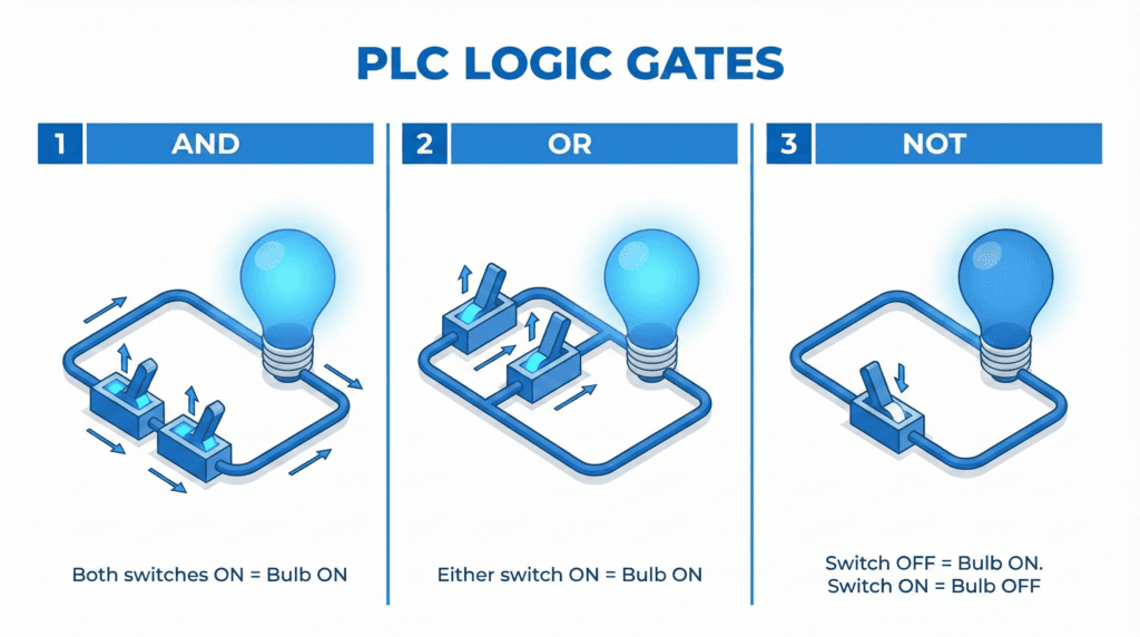
This is the most critical part of understanding how PLCs work. The CPU makes decisions using “Logic Gates”. Here are the three most common ones mentioned in our guide:
1. Logic AND (Both must be TRUE)
- Rule: Output turns ON only if Input A AND Input B are both ON.
- Example: A press machine will only start if the operator presses Button A (Left Hand) AND Button B (Right Hand) together. This ensures safety.
2. Logic OR (Either can be TRUE)
- Rule: Output turns ON if Input A OR Input B is ON.
- Example: A conveyor belt can be started from the Main Control Panel OR a Local Remote Station.
3. Logic NOT (Reverse)
- Rule: Output turns ON if Input is OFF.
- Example: A “System Healthy” light stays ON as long as the “Error Signal” is NOT present.
Summary
Understanding the basics of Inputs, Outputs, and Logic Gates is the first step. Once you grasp how PLCs work, simple logic allows you to build complex systems that run entire factories. It is not as complicated as it seems.
By combining these simple logic rules (AND, OR, NOT), engineers can build complex systems that run entire factories. And with user-friendly tools like the[Folks FC100-B], you can start building your own logic today.
Ready to practice your logic? Check out the [Folks FC100-B] and start your automation journey.