How to troubleshoot PLC ERROR/FAULT indicator lights
Think of the PLC as the human brain, sensors as sensory nerves (eyes, skin), and motors or contactors as muscles. An ERROR light is similar to a fever; it signals that something is out of sync between the brain’s instructions and the body’s response. The goal is to find the underlying “infection” rather than just masking the symptoms.
- Identifying the Error Type
● Fatal Error: Indicated by a solid red ERROR/FAULT light. The CPU immediately switches to STOP mode, and all outputs are disabled for safety. Common causes include
CPU hardware failure, memory errors, or watchdog timer errors.
● Non-Fatal Error: Indicated by a flashing ERROR light or an amber color. The machine might still run, but specific functions could fail. Common causes include loss of
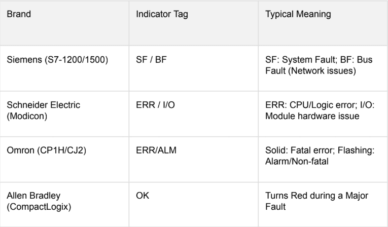
communication with I/O expansion modules, low backup battery, or mathematical errors in the program (e.g., division by zero). - Brand-Specific Indicators
While the principles remain the same, different brands use different terminology for their error lights:
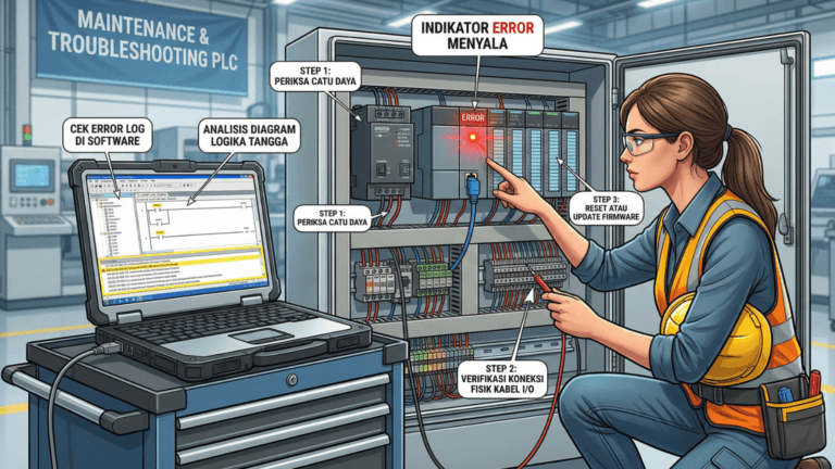
- The 4-Stage Troubleshooting Method
Stage A: Power Supply Inspection
Approximately 30% of PLC issues stem from unstable voltage. Verify that the input voltage (220V AC or 24V DC) meets manufacturer specifications using a calibrated multimeter.
Stage B: I/O Modules and Wiring
If the CPU is healthy but the machine is unresponsive, the issue often lies in the periphery. Check for loose wires caused by machine vibration and ensure sensors are clean and properly aligned.
Stage C: Software Diagnostics
This is the most precise method for identifying faults. Connect a laptop with the appropriate software (TIA Portal, CX-Programmer, etc.) and access the Diagnostic Buffer or Error Log. Specific error codes can pinpoint issues like a short circuit on a specific I/O point.
Stage D: Program Logic Verification
Review the logic for infinite loops or attempts to access restricted memory addresses, which can trigger processor faults. - Case Study: Solving Intermittent Failures
In a food production facility, a PLC faulted consistently every afternoon. The Diagnostic Buffer reported “Expansion Rack Communication Loss.” Investigation revealed that machine vibrations had loosened a communication cable, and rising afternoon temperatures caused cable material expansion, breaking the connection. The solution involved replacing the cable with a locking connector and installing vibration dampeners. Preventive Maintenance Checklist
● Replace Backup Batteries: Update batteries every 1-2 years to prevent program loss
during power outages.
● Maintain Cleanliness: Use a specialized electronics vacuum to remove conductive dust
from vents.
● Secure Terminations: Periodically tighten cable screws to counteract vibration-induced
loosening.
● Routine Backups: Maintain current program copies on secure cloud storage or external
drives.
Frequently Asked Questions
Q: Is it safe to power cycle the PLC during an Error?
A: While a power cycle may clear the symptom, it rarely addresses the cause. Always check the
Diagnostic Buffer before resetting.
Q: What if the RUN and ERROR lights are both on?
A: This typically indicates a minor fault or a ‘Force’ condition active on specific I/O addresses.
Conclusion
Reliable PLC troubleshooting depends on knowing where to find information. Treat diagnostic software as a primary tool and always perform fundamental physical checks first.