Industrial PLC Program Examples: Basic Logic, Ladder Diagram, and Factory Applications
Imagine a massive factory operating 24/7 without a single moment of fatigue. Behind the seamless motion of robotic arms, the relentless flow of conveyor belts, and the precision of high-speed bottle filling lines, there is one small yet incredibly powerful “brain” controlling it all: the PLC.
Let’s dive deep into what a PLC is and why this device has become the beating heart of the modern industrial revolution.
Here is the complete translation of your article into SEO-friendly English. I have strategically integrated the keyword “Industrial PLC Program Example” to ensure it ranks well for technical and automation-related searches.
What is an Industrial PLC Program and Why is it Vital for Automation?
PLC stands for Programmable Logic Controller. Put simply, a PLC is a specialized industrial computer designed to control machinery automatically.
Unlike fragile laptops or home computers, PLCs are built to be “rugged.” They are engineered to thrive in extreme environments—surviving heavy dust, high temperatures, and intense mechanical vibrations.
How a PLC Works (Input → Process → Output)
A PLC operates using a very straightforward logic cycle:
- Input: The PLC receives signals from sensors (e.g., temperature sensors, push buttons, or proximity switches).
- Process: The PLC checks the instructions or code programmed into its “brain.”
- Output: The PLC sends commands to external devices (e.g., starting a motor, opening a water valve, or triggering a warning light).
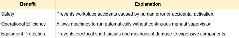
Why are PLCs Essential in Automation Systems?
Without PLCs, modern factories would be chaotic and inefficient. Here is why they are mandatory components:
- High Reliability: They rarely experience “hangs” or crashes compared to standard PCs.
- Flexibility: If you want to change the machine’s workflow, you don’t need to rip out wires. You simply update the software.
- Scalability: They can control anything from a single small machine to a massive, complex production line.
- Rapid Diagnostics: If a fault occurs, the PLC can pinpoint the exact problem via indicator lights or on-screen messages.
Defining PLC Programming in Manufacturing
Modern manufacturing no longer relies on human operators to press buttons every second. Behind the sophistication of automotive plants and food processing lines lies an electronic “brain” that works tirelessly.
Let’s explore the depth of PLC programming using simple language backed by strong technical references.
Real-World Industrial PLC Program Example
To give you a clear picture of how this works in a factory setting, here are the most common applications:
1. Conveyor Belt System
Scenario: The conveyor should only move if an object is detected on it and the “Start” button has been pressed.
- Input: Start Button and Weight Sensor.
- Logic: IF (Start Button is ON) AND (Weight Sensor is ON), THEN (Start Motor).
- Benefit: This Industrial PLC Program Example saves significant energy by ensuring the motor doesn’t run while empty.
2. Automatic Bottle Filling Machine
Scenario: Bottles move along a belt, stop precisely under a nozzle, fill up, and then continue moving.
- Input: Bottle Position Sensor and Liquid Level Sensor.
- Logic: IF (Bottle is under nozzle) THEN (Stop Motor & Open Valve). IF (Liquid is Full) THEN (Close Valve & Start Motor).
The Role of PLCs in Replacing Conventional Relay Systems
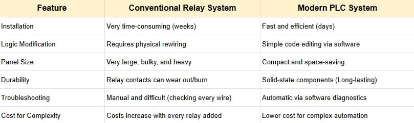
Before the digital era, machines were controlled by hundreds or even thousands of wires connected to devices called Relays. This was known as “Hard-wired Logic.”
What is a Conventional Relay System?
A relay is essentially an electrical switch. To run even a simple machine, technicians had to manually connect numerous relays using physical wires. The Main Problems:
- Massive Size: Control panels could be as large as a wardrobe just to manage one machine.
- Difficult to Modify: To change a machine’s function, you had to cut wires and re-cable the entire system.
- Nightmare Troubleshooting: Finding one broken wire among thousands could take days.
How PLCs Revolutionized the Industry
According to technology journals from ScienceDirect, the transition from relays to PLCs was a turning point for manufacturing efficiency. The PLC takes those thousands of physical wire connections and converts them into digital lines of code.
- From Physical Wires to Program Logic: In a relay system, “IF button is pressed, THEN light turns on” is created with copper wire. In a PLC, this relationship is built in software.
- Space Efficiency (Compactness): A PLC unit the size of a shoebox can replace a heavy rack full of relays, making the factory floor much cleaner.
- Speed of Diagnosis: Based on insights from Automation.com, PLCs feature internal diagnostics. If a machine stops, a programmer checks the computer screen to see which sensor is inactive, rather than testing every wire manually.
Simulation of Change: Relay vs. PLC
Industrial PLC Program Example: Replacing Relay Logic
In legacy systems, creating a flashing light required expensive, specialized relays. With a PLC, you only need a single line of code: the “Timer” instruction.
Scenario: Factory Automatic Gate Control
- Past (Relay): Required sensors, time relays, latching relays, and complex wiring just to ensure the gate wouldn’t close on a vehicle.
- Present (PLC): All safety logic is integrated into the Industrial PLC Program Example. If a sensor detects an object, the program immediately commands the motor to stop within milliseconds.
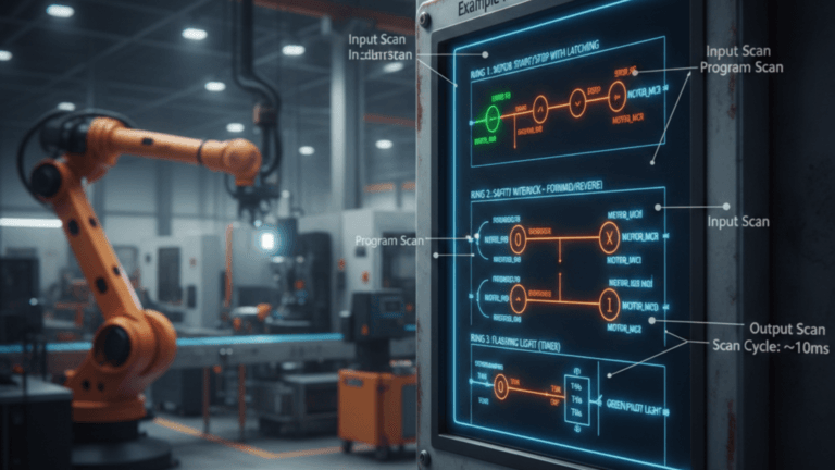
Understanding the Scan Cycle in Industrial PLCs
In the world of automation, a PLC doesn’t think like a human brain, which can process many random things at once. Instead, a PLC follows a highly disciplined and repetitive method called the Scan Cycle.
What is a PLC Scan Cycle?
The Scan Cycle is a continuous process where the PLC reads inputs, executes the program, and updates outputs. Imagine a factory supervisor walking in a fixed loop, checking every machine one by one, recording their status, giving new orders, and then repeating that exact same route indefinitely.
According to PLC Academy and Frank Petruzella’s standard textbook Programmable Logic Controllers, this scan occurs incredibly fast, usually measured in milliseconds (ms).
The 3 Main Stages of a Scan Cycle
Every time a PLC operates, it sequentially passes through these three stages:
- Input Scan (Check Input Status): The PLC checks the status of all input devices (sensors, buttons, switches). This status (ON/OFF) is stored in a temporary memory table called the Input Image Table.
- Note: The PLC will not “see” any changes to the inputs that happen during the next stages until the next cycle begins.
- Program Scan (Execute Program): This is where your Industrial PLC Program Example (such as Ladder Logic) is processed. The PLC reads the code line by line, from top to bottom, using the recorded input status to determine the required actions.
- Output Scan (Update Output): After calculating the logic, the PLC updates the output devices (motors, lights, or valves). Data is pulled from the Output Image Table and sent to the machine’s physical terminals.
Why Scan Cycle Speed Matters for Safety
Based on research from the International Journal of Control and Automation, scan speed is critical. If a sensor detects a human hand entering a dangerous cutting zone, the PLC must process that info and kill the power in less than 10–20 milliseconds to prevent an accident.
Industrial PLC Program Example in a Scan Cycle:
Machine Press Scenario:
- Input Scan: PLC detects the “Press” button pushed by the operator.
- Program Scan: PLC runs the logic: “IF button is pressed AND safety sensor is active, THEN lower the press.”
- Output Scan: PLC sends an electrical signal to the hydraulic valve to move the press down.
If the operator releases the button mid-way, the PLC will process the “Stop” command on the next scan cycle (which is only about 0.005 seconds later).
Simple Industrial PLC Program Example
To understand how a factory operates automatically, the best way is to look directly at how logic is programmed into the machine’s “brain.”
1. Motor Start-Stop System (Latching Logic)
This is the most basic yet most crucial program used to start a machine and keep it running until the “Stop” button is pressed.
- Inputs: Start Button (Normally Open), Stop Button (Normally Closed).
- Output: Electric Motor.
- The Logic: In the International Journal of Science and Research, this is called Latching. Since factory buttons are usually momentary “push buttons,” the motor would stop the moment you let go. Latching uses the “Motor ON” status to keep the circuit closed.
2. Automatic Packaging System (Sorting by Size)
Scenario: High items go to Path A; short items go to Path B.
- Input: Height Sensor (S1) and Presence Sensor (S2).
- Logic:
IF (S1 AND S2) THEN ACTIVATE PUSHER_A(Item is tall).IF (S2 AND NOT S1) THEN ACTIVATE PUSHER_B(Item is short).
Advantages of PLC Programs (Global Industry Standards)
According to technical articles from AutomationDirect, using an Industrial PLC Program Example for simple logic provides massive benefits:
- Safety Interlocks: Easily add code like “Don’t start the motor if the guard door is open.”
- Timers & Counters: PLCs can count production yields or delay actions—tasks that are difficult for hardware wiring.
- Reliability: Unlike humans, a PLC executes the exact same logic millions of times without fatigue or error.
Here is the professional English translation for the final section of your article, optimized with the keyword “Industrial PLC Program Example” to maintain high SEO relevance.
Interlock and Self-Holding Logic in Industrial Systems
In the world of automation, safety and operational sustainability are top priorities. To achieve this, engineers rely on two fundamental logic concepts: Self-Holding (Latching) and Interlock (Mutual Locking). Let’s break them down using simple language while sticking to international technical standards.
1. What is Self-Holding Logic?
Self-Holding (often called Latching) is a programming technique that allows an output, such as a motor, to stay powered even after the “Start” button is released.
According to technical articles from All About Circuits, this logic is vital because industrial push buttons are typically momentary—they only stay active while pressed. Without a Self-Holding Industrial PLC Program Example, an operator would have to hold the button for hours to keep the machine running, which is simply impossible.
- How it Works: The operator presses Start $\rightarrow$ the Motor turns on $\rightarrow$ the program uses a contact from the Motor itself to “bridge” the digital current, so when the button is released, the power continues to flow through this “locking” path.
2. What is Interlock Logic?
While Self-Holding keeps a machine running, an Interlock prevents two dangerous actions from happening at the same time. According to the International Journal of Advanced Research in Electrical, Electronics and Instrumentation Engineering, Interlocking is the most critical safety feature in automation.
- Real-World Example: Imagine a motor that can rotate Forward and Reverse. If both directions are activated simultaneously, the machine will short-circuit or suffer severe damage.
- Interlock Logic: “If the Motor is rotating Forward, the Reverse instruction must be cut (locked), and vice versa.”
Practical Application: The Lifter Machine
To illustrate this for your article, here is an Industrial PLC Program Example combining both logics for a goods lifter (elevator):
- Self-Holding: When the “Up” button is pressed once, the lift continues to rise to the target floor without needing to hold the button.
- Interlock: While the lift is moving Up, the Down button is completely disabled to prevent mechanical failure.
- Programming Detail: Inside the code for “Motor Up,” we insert a Normally Closed (NC) contact from “Motor Down.” This ensures that if the Down Motor is active, the Up Motor path is automatically severed.
Common Mistakes in Industrial PLC Programming
Even when following an Industrial PLC Program Example, beginners often fall into these three traps:
1. Inefficient Ladder Diagram Logic
Many beginners write programs that are too long and convoluted. In PLC programming, the principle is: The simpler, the better.
- The Error: Using too many “rungs” for a task that could be solved in one line. This slows down the PLC Scan Cycle.
- The Impact: Machine response becomes sluggish (lag). In high-speed machinery, even a $0.1$ second delay can cause production defects.
- The Solution: Use built-in function blocks like Timers or Counters instead of creating complex manual calculation logic.
2. Input and Output (I/O) Addressing Errors
This is the most frequent technical error when moving a design from paper to software.
- The Error: Entering the wrong address for a sensor or actuator (e.g., swapping the temperature sensor at
%I0.1with a pressure sensor at%I0.2). - The Impact: This can be extremely dangerous. Imagine the PLC commanding a cutting blade to drop because it thinks the item is in position, when in reality, the active sensor was actually an open safety door.
- The Solution: Always create an I/O Mapping table before programming and use clear “Tag Names” or comments for every address.
3. Neglecting Safety Interlocks
Ignoring Safety Interlocks is the most fatal mistake, involving human lives and machine integrity.
- The Error: Focusing only on “Normal Operation” and forgetting “Emergency Conditions.”
- The Impact: According to OSHA (Occupational Safety and Health Administration) reports, many industrial accidents occur because control systems lack adequate interlocking protection.
- The Solution: Always use Fail-Safe logic. Ensure every Industrial PLC Program Example includes instructions that kill all outputs if the Emergency Stop is pressed or a safety light curtain is triggered.
Here is the professional English translation for your conclusion, strategically integrated with the keyword “Industrial PLC Program Example” to maximize your article’s SEO performance.
Conclusion
As we conclude this in-depth exploration of the automation world, it is vital to draw a clear line between the code we write and the actual operation of a factory floor.
The Importance of Mastering Basic Logic Before Advanced Programming
Many are tempted to jump straight into advanced features like Industrial Cloud Systems or the Internet of Things (IoT), while neglecting the fundamentals. According to guidelines from the International Society of Automation (ISA), approximately 80% of automation system failures are not caused by hardware malfunctions, but rather by weak programming logic.
- Logic is the Language: Before mastering complex languages, you must understand the “grammar.” Concepts like Self-Holding, Interlock, and the Scan Cycle are the foundation that prevents you from creating conflicting programs.
- Safety Above All: Without a firm grasp of basic logic, a programmer might succeed in starting a machine but fail to stop it safely during an emergency. This is why every Industrial PLC Program Example must prioritize safety protocols first.
PLC Programming as the Foundation of Modern Industrial Automation
The PLC is not merely an outdated tool; it has evolved. According to journals from ScienceDirect, the PLC remains the gold standard in the manufacturing industry due to its reliability, which far surpasses that of a standard computer.
- The Bridge to Industry 4.0: Even when discussing a simple Industrial PLC Program Example, that code serves as the bedrock for the smart systems of the future. Without stable PLC instructions, sensor data could never be sent to servers for AI analysis.
- Efficiency and Scalability: PLCs allow small factories to scale into industrial giants by simply adding modules and updating programs without the need to overhaul the entire mechanical infrastructure.