What is PLC Ladder Diagram? A Simple Guide to Industrial Programming
If you are just stepping into the world of industrial automation, you will frequently encounter the term Ladder Diagram. While it sounds highly technical, the concept is actually quite intuitive and visual.
In this guide, we will break down what is a PLC Ladder Diagram, how it works, and why it remains the “gold standard” for controlling the machines that run our world.
The Role of Ladder Diagrams in Industrial Control
Think of a factory. The PLC (Programmable Logic Controller) acts as the “brain.” If the PLC is the brain, then the Ladder Diagram (LD) is the language we use to give that brain instructions.
Its primary roles include:
- Automated Control: Managing when a machine starts, stops, or moves based on sensor data.
- Logic Bridge: Translating physical actions (like pressing a button) into digital commands the machine understands.
- Interlocking (Safety): Ensuring a motor won’t start if a safety door is open, protecting both workers and equipment.
Why is Ladder Diagram the Most Popular PLC Language?
Despite the rise of text-based coding (like C++ or Python), Ladder Diagram remains the king of the factory floor. Here’s why:
1. It Mimics Electrical Schematics
Before PLCs existed, factories used thousands of physical wires and magnetic relays. Electricians were already experts at reading wiring diagrams. Because the PLC Ladder Diagram was designed to look exactly like those old blueprints, technicians didn’t have to learn “coding” from scratch—they just had to learn a digital version of what they already knew.
2. Effortless Troubleshooting
In a factory, “downtime” means losing money. When a machine stops, a technician needs to know why—instantly. In a Ladder Diagram, the path of “electricity” glows (usually green on the screen).
The benefit: A technician can look at the screen and say, “Oh, Sensor A isn’t triggering, that’s why Motor B won’t start.” This is much faster than scrolling through thousands of lines of text code.
3. A Global Standard (IEC 61131-3)
Ladder Diagram isn’t just a trend; it’s an international standard. If you can read a Ladder Diagram on a Siemens PLC, you can easily adapt to an Allen-Bradley, Mitsubishi, or Omron system.
Understanding the Core Concepts
You only need to understand three main components to master the “ladder” structure:
The Rails and Rungs
- Rails (Vertical): Think of the two vertical lines as the “power poles.” The left rail is the positive/hot side, and the right rail is the neutral/ground side. Logic flows from left to right.
- Rungs (Horizontal): These are the “steps” of the ladder where you place your instructions. A program can have hundreds of rungs depending on the machine’s complexity.
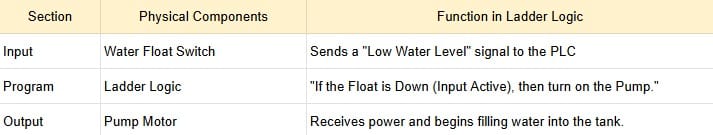
The Logic Flow (Input & Output)
- Inputs (Left Side): These represent switches, sensors, or buttons.
- Outputs (Right Side): These represent the “action” items, like motors, lights, or valves (often called Coils).
Essential Symbols You Need to Know
To understand what is a PLC Ladder Diagram in practice, you must recognize these three basic symbols:
- NO Contact (Normally Open):
- Symbol: $| \ |$
- Logic: Think of a doorbell. Electricity only flows when you press it.
- NC Contact (Normally Closed):
- Symbol: $| / |$
- Logic: Think of an Emergency Stop button. It allows electricity through by default and only “breaks” the circuit when you press it.
- The Coil (Output):
- Symbol: $( \ )$
- Logic: This represents the device you want to turn on. If the logic path to the left is complete, the coil activates.
How the PLC Processes Your Program (The Scan Cycle)
A PLC doesn’t “read” code once and stop. It operates in a continuous Scan Cycle that happens thousands of times per second:
- Input Scan: The PLC checks which buttons are pressed.
- Program Execution: It reads your Ladder Diagram from Top to Bottom and Left to Right.
- Output Scan: It turns the physical motors or lights on or off.
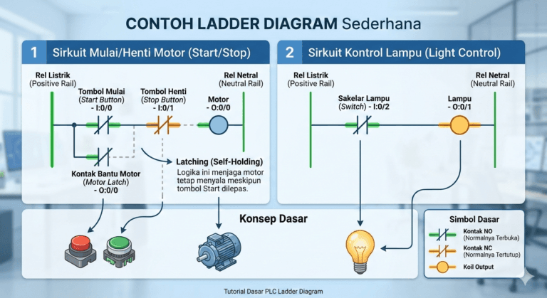
Real-World Example: The “Self-Holding” Motor Circuit
The most common logic in any factory is the Start/Stop circuit.
- You press Start (NO Contact) $\rightarrow$ The Motor (Coil) turns on.
- Because you don’t want to hold the button down all day, we add a “Latch” (a contact from the motor itself) in parallel with the Start button.
- Now, even when you release the Start button, the motor stays on because it “holds” its own circuit closed.
- The only way to stop it is to press the Stop (NC Contact), which breaks the flow.
Conclusion
Understanding what is a PLC Ladder Diagram is the first step toward becoming a master of industrial automation. It turns complex electrical wiring into a clean, visual, and easy-to-troubleshoot digital format. By mastering Input $\rightarrow$ Logic $\rightarrow$ Output, you hold the key to controlling almost any automated machine in the world.