Mastering How to Read PLC Input/Output Wiring Diagrams

In industrial automation, the ability to read wiring diagrams is a foundational skill. It is the universal language that connects program logic with physical machine actions. Many talented technicians excel at programming but struggle when facing a complex stack of wiring schematics in the field. This article provides a deep dive into how to read PLC input output wiring diagrams efficiently, covering everything from core fundamentals to technical architecture.
1. Understanding the Basic Anatomy of a PLC Wiring Diagram
Before diving into the technical details, imagine a PLC as the brain of a human body. Inputs are the sensory nerves (eyes, skin) that send information, while Outputs are the muscles that execute actions. The wiring diagram is the neural map that connects them.
A Simple Analogy: The Home Light Switch
Imagine you want to turn on a light using a switch:
- Input: The position of the switch (ON or OFF).
- PLC: The logic that decides, “If the switch is pressed, then flow electricity to the light.”
- Output: The illuminated light bulb.
In an industrial setting, the components are definitely more complex (such as ultrasonic sensors or induction motors), but this fundamental principle of “information flow” remains exactly the same.
2. Identifying Key Components in PLC I/O Schematics
When you open a schematic sheet, your eyes must immediately recognize several standard symbols and codes. We divide these into two main categories:
A. Input Modules (Incoming Information)
Inputs provide the real-time status from the field to the PLC. There are two primary types you need to know when learning how to read PLC input output wiring diagrams:
1. Digital Inputs (DI)
Digital inputs handle discrete “Yes” or “No” (0 or 1) signals. Examples include push buttons, limit switches, and proximity sensors.
To read these diagrams accurately, you must understand two simultaneously working systems inside a DI module:
- Optoisolator Technology: DI modules use an optoisolator (a combination of an LED and a phototransistor) to physically separate the field circuit from the CPU unit. The sensor signal transmits via light rather than a direct electrical current. This implementation is crucial for enhancing system trustworthiness; if a voltage surge or electrical interference occurs on field devices, the optoisolator isolates the damage, protecting the sensitive components of the CPU.
- Current Configuration (Sinking vs. Sourcing): Sinking and sourcing classify the wiring methods that determine the direction of conventional current flow at the Digital Input terminals.
- Sinking Input (NPN): The PLC input terminal acts as a current drain. Current flows from the field device (sensor) into the PLC module. This configuration requires you to connect the Common terminal to the Positive (+) power supply pole.
- Sourcing Input (PNP): The PLC input terminal acts as the current source. The PLC pushes current out of the module toward the field device. This configuration requires you to connect the Common terminal to the Negative (-) power supply pole.
2. Analog Inputs (AI)
Unlike discrete digital inputs, Analog Inputs process continuous signals that represent physical variables in the field. This module acts as a translator, converting electrical values into numerical data that the PLC CPU can process.
- Industrial Signal Standards (Current vs. Voltage): In professional practice, wiring diagrams will feature two dominant types of analog signals:
- Current Signal (4-20mA): The industry gold standard. Its main advantages are high immunity to electromagnetic interference (noise) and built-in wire break detection. If the current reads 0mA, the system automatically identifies a physical connection failure.
- Voltage Signal (0-10VDC): Typically used for short-distance device integration. This signal is highly susceptible to voltage drop over long cable runs, requiring stricter cable shielding protections.
- A/D Conversion Mechanics and Resolution: AI modules operate on the principle of Analog-to-Digital (A/D) conversion. The module’s resolution determines how precisely the PLC can read physical value changes:
- Bit Resolution: Higher bit ratings (such as 12-bit or 16-bit) allow for a finer division of the analog value into digital data. For example, at a 12-bit resolution, a 4-20mA signal converts into a digital range of 0 to 4095.
- Sampling Rate: This defines how fast the module updates digital data from the analog signal. High sampling rates are critical for fast-changing processes, such as pressure tracking in hydraulic systems.
B. Output Modules (Command Execution)
Outputs represent the commands sent from the PLC to external field devices:
- Digital Outputs: Turn devices strictly ON or OFF. Examples: Solenoid valves, magnetic contactors, and indicator lights.
- Analog Outputs: Regulate speed, pressure, or positioning by sending continuous signals. Example: Sending a signal to a VFD (Variable Frequency Drive) to control motor speed.
Read Also : Industrial PLC Program Examples: Logic Fundamentals, Ladder Diagrams, and Factory Applications
3. Step-by-Step Guide to Reading Input Diagrams
When learning how to read PLC input output wiring diagrams, we highly recommend always starting from the left or the top of the schematic, following the voltage flow.
- Identify the Power Supply: Look for terminals labeled L+ (+24VDC) or L1 (220VAC). Almost every PLC input requires a reference voltage to operate.
- Locate the Common (COM): This is a critical step. In DC systems, determine whether your PLC uses a Sinking (Common to Negative) or Sourcing (Common to Positive) configuration. Misreading this specific detail can cause system failure or permanently damage the input module.
- Trace the Address: Every wire connects to a terminal with a unique code, such as
I:0/0,X0, or%I0.0. This code represents the exact memory address used inside the PLC software. - Check the Contact Type: Determine whether the field sensor is Normally Open (NO) or Normally Closed (NC). This tells you whether current flows when the sensor is active or at rest.
4. How to Read Output Wiring Diagrams
Reading the output side requires even higher precision because you are dealing with significantly larger electrical loads.
Understanding PLC Output Types
We frequently remind our clients to clearly distinguish between these three output types on a schematic:
- Relay Outputs: Highly flexible, handling both AC and DC voltages. You will easily recognize them by the mechanical switch symbol on the diagram.
- Transistor Outputs: Designed exclusively for DC loads. Use these for fast-switching applications like PWM (Pulse Width Modulation) or servo motor control.
- Triac Outputs: Designed strictly for switching AC loads.
The Reading Workflow
- Verify the Load Voltage: Do not let the internal electronics fool you; even if a PLC uses 24VDC internally, a relay output might be breaking a high-voltage 220VAC line for a motor starter.
- Locate Circuit Protection (Fuse/MCB): Always check where the circuit breakers or fuses sit before the wire reaches the final field component.
5. Case Study: Automatic Water Tank Filling System
To give you a clearer picture of how to read PLC input output wiring diagrams, let’s analyze a simple, real-world system that we frequently optimize.
Scenario: A water tank utilizes two level sensors (Low & High) and one automated pump.
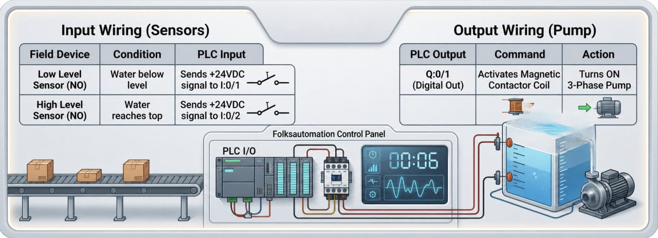
PLC Input and Output Wiring Analysis
1. PLC Input Wiring Analysis
The diagram shows two sensor wires connected to terminals I:0/1 (Low Level) and I:0/2 (High Level).
- Operation: When the water level drops below the I:0/1 sensor, the contact closes and sends a 24V signal to the input module. The PLC then registers a “Tank Empty” status.
2. PLC Output Wiring Analysis
Terminal Q:0/1 connects directly to the Magnetic Contactor (MC) coil.
- Operation: The PLC activates output Q:0/1, sending current to the MC coil. This action closes the main MC contacts and starts the 3-phase water pump.
Important Safety Note: The PLC does not power the motor directly. It uses a magnetic contactor as an intermediary because the 3-phase pump’s high current draw will damage the PLC output module.
6. Pro Tips: Avoiding Common PLC Wiring Errors
Based on years of field experience, keep this PLC troubleshooting checklist handy:
- Always Check the Legend and Standards: While designers have unique styles, professional schematics must follow global standards like IEC 60617 (European) or NFPA 79 / ANSI (American). Never assume; always review the symbol chart on the first page of the document.
- Verify Wire Ferrule Numbers: Cable colors can deceive you in legacy panels. For instance, technicians often use leftover blue wires for AC phases during rushed modifications, even though standards reserve blue for DC control. Trust the wire label numbers (ferrules), not the insulation color.
- Use a Multimeter: When in doubt, perform a continuity test. Ensure the wire from the physical push button physically reaches the designated PLC input terminal.
- Differentiate Ground from Common: Ground provides equipment safety protection, while Common acts as the current return path for the circuit. Mixing them creates electrical noise that disrupts PLC logic and causes intermittent CPU faults.
Conclusion
Reading PLC I/O wiring diagrams requires technical skill and systematic logic. By mastering sinking vs. sourcing configurations, recognizing output types, and tracing wire numbers, you can troubleshoot and install automation systems much faster.
Accurate documentation solves half of your automation problems. Mastering diagram reading gives you the key to maintaining efficient control systems. Keep practicing with different manufacturer schemas—such as Siemens, Mitsubishi, or Allen-Bradley—to sharpen your field intuition.