How to Create PLC Ladder Diagrams for Beginners (A Complete and Easy-to-Understand Guide)
Before diving deeper, let’s first understand what a ladder diagram is. A Ladder Diagram is a graphical programming language used in PLCs to design logic-based control systems for various industrial applications. Understanding these fundamentals is the essential first step in learning how to create a PLC ladder diagram.
What is a PLC Ladder Diagram? Why is it Widely Used in Industry?
Before you learn the technical steps of how to create a PLC ladder diagram, it is important to understand why this specific language is the global standard for industrial automation.
1. Intuitive and Easy for Electricians to Understand
Ladder Diagrams (LD) closely resemble conventional electrical schematic drawings that electricians and mechanical engineers study from the start of their careers. Because it looks like relay logic and electrical circuits, technicians and maintenance teams can easily read and understand the logic without needing to learn high-level text-based programming languages first.
2. Clear and Direct Logic Visualization
Ladder diagrams provide a definitive visual representation of control logic that eliminates ambiguity during the programming process. By utilizing Normally Open (NO) and Normally Closed (NC) contacts to represent physical or logical input states, the diagram acts as a direct mapping of the system’s operational requirements. This method allows you to define specific input conditions that must be met before a signal can propagate through the network, effectively creating a clear boundary between operational and non-operational states.
The output conditions are defined by coils, which serve as the final logical destination within a rung. When all input conditions on a rung satisfy the defined logical state, the coil is energized, effectively creating a direct cause-and-effect relationship that is observable in real-time. This structure is superior to text-based programming because it prevents logic-chain errors that are often hidden in complex lines of code, as the physical positioning of elements dictates the execution path.
The flow of logical “power” through the rungs acts as the backbone of ladder logic, dictating the precise sequence of operations. As you move from the left power rail to the right, you can trace the state of every input and output, which significantly reduces the time required for troubleshooting. This structural clarity is essential for beginners, as it transforms abstract logical requirements into a rigid, manageable, and highly debuggable visual framework.
3. Internationally Defined IEC 61131-3 Standard
The inclusion of the Ladder Diagram within the IEC 61131-3 international standard establishes it as a foundational programming language for global industrial automation. This formal standardization dictates a rigid and structured framework for development, ensuring that logical operations are executed with a consistent methodology regardless of the application’s complexity. By adhering to this universal protocol, developers can operate within a predictable environment where the fundamental principles of control logic remain immutable, thereby increasing the reliability of the industrial control system.
Interoperability remains a significant advantage of this standard, as it provides near-universal compatibility across major programmable logic controller manufacturers such as Siemens, Allen-Bradley, and Mitsubishi. Because the underlying syntax and logical conventions are governed by an international consensus, the barriers to hardware migration are effectively minimized. This compatibility ensures that the logic programmed on one platform can be interpreted or adapted with minimal friction when transitioning to a different hardware architecture, which is critical for maintaining long-term operational continuity.
For professional engineers, the IEC 61131-3 standard drastically reduces the learning curve when shifting between disparate control systems. Since the fundamental logical building blocks are standardized, an engineer who masters the syntax in one environment does not need to relearn the core mechanics when working on another brand’s platform. This universality promotes a more efficient engineering workflow, allowing technical personnel to focus on the optimization and safety of the process rather than the nuances of proprietary coding structures.
4. Broad Compatibility Across the Market
The majority of modern PLCs and engineering communities support Ladder Diagram as the primary or default language. Because of this widespread support, many manufacturers stick to Ladder rather than less common languages.
5. Faster Troubleshooting and Debugging
With its graphical structure, technicians can instantly see the “power flow” in real-time. You can quickly identify which part of a process is stuck or which line of code is throwing an error. This speeds up the identification and repair process on the factory floor, which is critical for maintaining constant uptime.
6. Industry Habit and Knowledge Legacy
In many parts of the world, engineering talent is raised on traditional relay logic. Consequently, industries find it more efficient to use Ladder Logic rather than switching entirely to text-based languages like Structured Text (ST) or Function Block Diagrams (FBD).
Fundamentals to Master Before You Create a PLC Ladder Diagram
To master how to create a PLC ladder diagram, you must understand the three core components:
1. Inputs Inputs are the parts of the PLC that receive signals from the outside world, such as sensors or buttons. Their main function is to gather information from the industrial process and send it to the CPU (the “brain” of the PLC where all decisions are made).
- Examples: Pressure sensors, limit switches, temperature sensors, push buttons, and proximity sensors.
- These inputs are converted into digital or analog signals (such as 0-10V or 4-20mA) that the PLC understands. Each input has a unique memory address.
2. Outputs Outputs are the components that send commands from the PLC to external devices after the logic has been processed.
- Examples: Motors (ON/OFF), relays/contactors, indicator lights, solenoid valves, and alarms.
- The output takes the result of the program execution and triggers the corresponding physical device.
3. PLC Memory Concepts Memory is the essential element that stores everything required for the PLC to work effectively. The memory architecture of a Programmable Logic Controller (PLC) serves as the core repository for all data and instructional sets necessary for autonomous system operation. The primary segment, the user program memory, holds the compiled ladder diagram logic, which dictates the systematic execution of control sequences. This memory area is non-volatile or battery-backed in most industrial controllers to ensure that the machine’s control logic remains intact during power cycles, thereby maintaining operational integrity without requiring manual program restoration.
Beyond the program logic, the PLC maintains a dynamic memory section dedicated to the real-time status of input and output modules. This I/O image table continuously synchronizes the physical state of field devices—such as sensors, switches, and actuators—with the controller’s internal processors. By capturing the state of these signals at the start of each scan cycle, the PLC ensures that the logical operations performed on the ladder diagram are based on accurate and current field data, which is critical for precise system synchronization.
The final memory segment is allocated to internal data storage, which manages the transient variables required for complex logical operations. This area houses critical elements such as timers, counters, and internal markers that track elapsed durations, event frequencies, and auxiliary logical states. Furthermore, the inclusion of data registers allows the PLC to store numerical values, setpoints, and diagnostic parameters that may be manipulated by the program logic during execution, providing the necessary infrastructure for advanced data handling and process control.
Types of PLC Memory
PLC memory is categorized based on its function to ensure the system operates reliably even during power cycles. Understanding these memory types is a vital step in learning how to create a PLC ladder diagram that is both stable and efficient.
This is a common point of confusion for beginners, but mastering it is the first real step in learning how to create a ladder diagram for a PLC. Below is the English translation, optimized for clarity and technical accuracy.
Understanding NO (Normally Open) and NC (Normally Closed) Contacts
1. NO (Normally Open)
Normally Open means that in its default state (unpressed or inactive), the contact remains open.
In a Ladder Diagram, an NO contact will:
- Block the logic flow (False / 0) when the input is OFF.
- Pass the logic flow (True / 1) when the input is ON.
To put it simply: When the button is pressed → the signal enters → the NO contact “closes” → the output can activate.
Common Examples:
- START Push Buttons
- Sensors that activate upon detecting an object
Ladder Diagram Symbol: —| |—
2. NC (Normally Closed)
Normally Closed is the exact opposite. In its default state, this contact is closed.
In a Ladder Diagram, an NC contact will:
- Pass the logic flow when the input is OFF.
- Open (blocking the logic flow) when the input is ON.
To put it simply: When the signal becomes active, the path is actually broken.
Common Examples:
- STOP Push Buttons
- Emergency Stops (E-Stops)
- Safety Sensors
Ladder Diagram Symbol: —|/|—
Crucial Distinction: Physical Contacts vs. Program Contacts
This is where many beginners get confused. When learning how to create a ladder diagram for a PLC, remember that NO and NC symbols in your software do not always have to match the physical button type.
What matters is the signal logic arriving at the PLC:
- The Scenario: A STOP button is almost always wired as a physical NC component for safety reasons (so that if a wire breaks, the machine stops).
- The Logic: Because a physical NC button sends a “1” (High) signal to the PLC when not pressed, you must account for that in your code.
- The Lesson: Don’t just memorize the symbols; understand the flow of the electrical signal.
Pro Tip: Always verify your physical wiring before finalizing your ladder logic to ensure your “Normally Closed” safety features actually behave as intended
Basic Ladder Logic Symbols
Here is the translation into English, structured to help you understand how to create a ladder diagram for a PLC using fundamental logic gates.
Logic Concepts: AND, OR, and NOT in Ladder Diagrams
To make it easy, imagine a Ladder Diagram is like the electrical wiring in a house. The electrical current flows from left to right to power a “load” (such as a light or a motor).
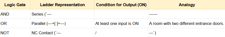
1. AND Logic (Series Logic)
Think of AND Logic as two switches installed in a row (Series). For the light to turn on, Switch A AND Switch B must both be closed (pressed).
- Real-world Example: A safety system for a cutting machine. The operator must press two buttons simultaneously with both hands to make the machine work. This ensures their hands are away from the blade.
- How it works: If only one switch is pressed, the electrical current is blocked halfway. The light will not turn on.
OR Logic (Parallel Logic)
In OR Logic, the switches are installed in a branched or side-by-side configuration (Parallel). Here, you have a choice: press Switch A OR Switch B, and the light will still turn on.
- How it works: The current has “alternative paths.” If the top path is broken but the bottom path is connected, the current still reaches the light.
- Real-world Example: A staircase light. You can turn the light ON from the switch at the bottom of the stairs or from the switch at the top. If either one is pressed, the light turns ON immediately.

NOT Logic (Inversion Logic)
NOT Logic is unique because it operates on the principle of “opposites.” In a Ladder Diagram, we achieve this by using a Normally Closed (NC) contact, which is typically represented with a diagonal slash through it.
- How it works: In its normal state (when the switch is NOT pressed), the current actually flows, and the light stays ON. However, the moment you press the switch, the circuit is broken, and the light turns OFF.
- Real-world Example: An Emergency Stop button. Under normal conditions, the machine must run continuously. But as soon as a hazard occurs and the button is pressed, the NOT logic cuts the power so the machine stops immediately.
PLC Ladder Diagram Structure and How to Read It
What is a “Rung” in a Ladder Diagram?
If a Ladder Diagram is a “ladder,” then a Rung is an individual step or rung of that ladder. Each Rung represents a single line of instruction or one logic statement. The PLC reads these rungs one by one, from the very top rung to the bottom, in a repetitive cycle called scanning.
- One Rung = One Function: Usually, one rung is used to control one specific output (coil).
- “True” Logic: If the conditions on the left side are met, the logic “current” will flow across the rung to activate the output on the right.
Logic Flow: From Left to Right
In the PLC world, we use the term Power Rails. These are the two vertical lines on the far left and far right.
- Left Rail (Power Rail): Imagine this as the positive terminal or the power source.
- Right Rail (Neutral Rail): This is the negative terminal or the return point.
- Left-to-Right Flow: PLC logic always flows from the left rail toward the right rail. The current can only reach the right side if all “switches” (contacts) along the rung are closed or active.
Key Point: The PLC is not actually flowing 220V electricity through its code. It is virtual logic that mimics real electrical circuits to make it easier for technicians and engineers to understand.
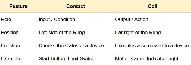
The Difference Between Contacts and Coils
These are the most fundamental components you will encounter. To put it simply: Contacts are Inputs, and Coils are Outputs.
1. Contacts (Inputs)
Located on the left side of the rung. Contacts represent the conditions that must be satisfied (such as sensors, buttons, or switches).
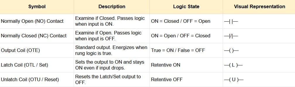
- Normally Open (NO): Symbolized as
—| |—. Current will not pass unless there is a “command” (e.g., a button is pressed). - Normally Closed (NC): Symbolized as
—|/|—. Current passes by default and will be cut off if there is a “command” (e.g., a sensor detects an object).
2. Coils (Outputs)
Located at the far right end of the rung. The symbol is usually parentheses —( )— or a circle.
- A Coil represents the device you want to control, such as a lamp, motor, solenoid, or an internal memory bit.
- If the logic path from the left is “connected” all the way to the Coil, the Coil becomes ON (Energized).
Quick Comparison: Contacts vs. Coils
Step-by-Step Guide: How to Create a PLC Ladder Diagram
Many international experts (such as those from RealPars or PLC Academy) emphasize the importance of preparation before you even touch the programming software. Here are the practical steps to building a Ladder Diagram from scratch:
1. Define the Control System Objective
Before opening your laptop, you must know exactly what the machine is supposed to do. This is often referred to as the Sequence of Operation.
- Ask yourself: “What triggers the machine to start?” and “Under what conditions must the machine stop?”
- Pro Tip: Create a simple sketch or a Flowchart. For example: “If the Start button is pressed, the conveyor runs. If the sensor detects an item, the conveyor stops for 5 seconds, then starts again.”
2. Identify Inputs and Outputs (I/O)
Once you understand the operation, inventory all the hardware connected to the PLC. In the industrial world, this is called I/O Mapping.
- Inputs: Components that provide information to the PLC (Buttons, Sensors, Limit Switches).
- Outputs: Components driven by the PLC (Motors, Lights, Solenoids, Buzzers).
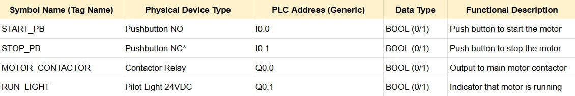
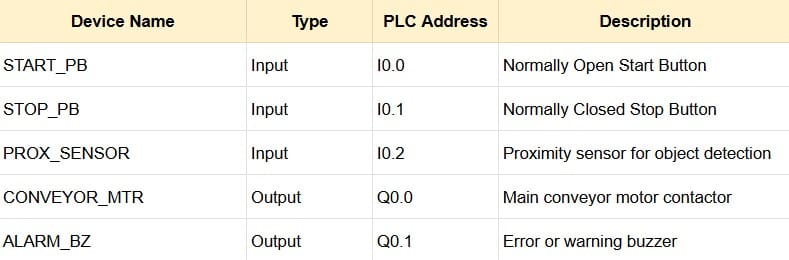
3. Create a Memory Type Table (Address Tagging)
To help you organize your thoughts and prepare for the spreadsheet export, use this English template for your I/O Mapping:
4. Creating the Basic Logic on the First Rung
Start with the most fundamental element: the Start/Stop System. Avoid building complex logic right away. Focus on one primary function first to prevent confusion when troubleshooting errors.
- Latching (Self-Holding): Since a push button only sends a momentary signal, you need an auxiliary contact from the Output to “lock” the logic flow. This ensures the motor stays running even after the button is released.
5. Adding Interlocks and Safety Systems
This stage distinguishes an amateur programmer from a professional. An Interlock is a safety “lock” that prevents two opposing conditions from occurring at the same time.
- Interlock Example: A motor must not start if the safety gate (guard door) is open.
- Emergency Stop: Ensure there is logic that disconnects all Outputs if the emergency button is pressed. Use NC (Normally Closed) contacts for maximum security (fail-safe design).
Expert Quote: “Programming is 20% making it work, and 80% making it safe.”
6. Simulation and Program Testing
Never send a program directly to a live machine! Use the Simulator features available in PLC software (such as RSLogix Emulate, ISPSoft Simulator, or TIA Portal Simulation).
- Test Worst-Case Scenarios: What happens if a sensor fails? What happens if the Stop button is pressed in the middle of the process?
- Debug: If something doesn’t work as expected, fix the logic in the simulator until it runs perfectly smooth.
Common Mistakes When Creating a PLC Ladder Diagram
To save you from experiencing the same errors, let’s discuss the most frequent mistakes made during Ladder Diagram development and how to avoid them:
1. Misusing NO and NC Contacts
This is the most common “trap” for beginners. It usually happens when we confuse the physical state of a switch in the real world with the logic symbol in the software.
- The Mistake: Using a physical Emergency Stop button that is NC (Normally Closed), and then also using an NC symbol in the program logic.
- The Effect: The logic becomes inverted. When the button is pressed, the machine runs; when released, the machine stops.
- The Solution: Always visualize the flow of the “logic current.” If the physical button is already passing current (NC), you simply use an NO symbol (
—| |—) in the program to detect that current.
2. Failing to Create Safety Interlocks
This is a fatal error that can destroy hardware or endanger operators. An Interlock is a locking system that prevents two opposing actions from occurring simultaneously.
- Case Example: You are programming a motor for Forward and Reverse. If you forget the interlock and both buttons are pressed at once, the motor could short-circuit or burn out.
- The Correct Way: Insert an NC contact of the “Reverse” Output into the “Forward” Output path. This ensures that as long as the motor is reversing, the forward path is automatically disconnected by the system.
3. Logic That Is Too Complex and Hard to Read
Many beginner programmers feel that the longer and more branched a rung is, the more “pro” they look. However, the core principle in the industry is KISS (Keep It Simple, Stupid).
- The Mistake: Piling too many conditions (AND, OR, NOT) into one single, massive rung. This makes troubleshooting a nightmare for maintenance technicians.
- The Solution: Break the logic into several simple rungs. It is much better to have 10 easy-to-read rungs than 2 giant rungs that cause headaches.
4. Not Commenting the Program
Imagine you have to fix a machine two years from now, and you see thousands of addresses like I:0/1 or O:0/5 without any description. You will surely regret not labeling them.
Pro Tip: According to international standards, every rung should have at least one line of description explaining its function.
The Mistake: Being lazy about adding names (Labels/Tags) and descriptions to every address.
The Impact: Repair time becomes significantly longer, and there is a high risk of making the wrong modification.
Here is the translation into English, incorporating professional standards on how to create a ladder diagram for a PLC that is clean, efficient, and industry-ready.
Tips for Creating Neater and Professional PLC Ladder Diagrams
According to experts from SolisPLC and AutomationDirect, clean code is an investment. If a machine breaks down at 3 AM, organized code will save the technician’s time (and your reputation). Here are the professional secrets to making your Ladder Diagram look like it was built by a pro:
1. Use Consistent Address Naming
Don’t let your program be filled with mysterious codes like I:1/0 or M0.1 without names. In modern industry, we use Tag-Based Programming.
- Use Descriptive Names: Instead of just
Sensor1, useInlet_Bottle_SensororLS_Upper_Limit_Switch. - Naming Standards: Use a consistent format, such as
Prefix_Location_Function. Example:IN_Panel_StartPB(Input from the Panel, Start Push Button). - CamelCase or Snake_case: Choose one and stick to it. Examples:
MainPumpMotorormain_pump_motor.
2. Separate Logic by Function
Do not pile all your logic into one single, massive Main Routine. This is a common beginner’s mistake. International programmers typically divide programs into “Sub-Routines” or small modules.
- Filing Cabinet System: Imagine your program is a filing cabinet. Separate it by function:
- Input Routine: Specifically for organizing signals from physical sensors.
- Alarm/Safety Routine: Specifically for protection logic.
- Auto/Manual Routine: For machine movement logic.
- Output Routine: The final path before activating actuators.
- The Benefit: If there’s an issue with the pump, you only need to open the “Pump” folder, saving you from scrolling through thousands of lines.
3. Document Every Rung Clearly
Documentation isn’t just about what the rung does, but why the logic was designed that way.
- Rung Comments: Every rung or group of rungs must have a comment.
- Bad: “Turn on the motor.” (This is already obvious from the symbol).
- Good: “Energizes the Conveyor Motor if Sensor A is active AND the safety gate is closed.”
- Revision Log: If you modify someone else’s program (or your own), add a small note: “Feb 23, 2026 – Added a 2-second delay to prevent bottle spills.”
Conclusion: Mastering the Art of PLC Ladder Logic
Creating a Ladder Diagram is like building a bridge between the digital world (software) and the physical world (machinery). By following a structured process—defining goals, mapping I/O, and implementing safety systems—you will produce a program that is not only functional but also safe and easy to maintain.
Remember: A great program is one that even the most junior technician can read and understand without having to call you for help.